Goals
- Develop a tool to construct Camera objects from collections of fits files (or MEFs).
Background and strategic fit
The camera team would like to use the DM stack to analyze their test data. They can do this using obs_file, or by defining Camera objects by hand, but it would be much nicer to have a tool to create the appropriate Camera object from the data directly.
Requirements
| # | Title | User Story | Importance | Notes |
|---|---|---|---|---|
| 1 | Support both amp per file and sensor per file with amps in extensions. There are actually 4 cases:
| The data are currently in MEFs, one per sensor. This could change so should be flexible. | Must have | |
| 2 | Should use a minimum of external ancillary information. | The goal will be to create the Camera only using primarily information in the FITS headers. Amp and Detector information will be taken from the header with some values possibly given global defaults in the config. Camera information will be supplied in a config to the task. | Must have |
|
User interaction and design
The current design of the image format from the camera team is here: https://confluence.slac.stanford.edu/display/LSSTCAM/Draft+File+Specification+for+EO+Test+Images
Also see the notes from an Oct 8 meeting
This could be informed by the DM effort to implement this tool. I'm first going to design the chip per file with an amp per extension. We can see how that fits with a more general design.
Design
- Inherit from CmdLineTask. This provides --config and --configfile command line options, but will also be callable
- --showCamera: will display the camera in ds9
- --writeCamera=destination: will save the camera description so it can be reused later.
- It may not be possible to inherit directly from CmdLineTask since it requires a repository. In that case, we will add a slimmed down ArgumentParser that doesn't require a mapper. This may be generally useful anyway.
- Per chip info will be in the header.
- The assumption is that the chip level info will be in the Primary Header
- Unfortunately this will require some custom keys (indicated with *)
- We need to make sure we are not colliding with accepted standards.
- Camera level info will come from a config (or specified with the --config option on the command line).
- Mapping between key names will happen via a key map taken from the config. This will simply by a dictionary mapping default name (key) to name in the data (value).
- There will also be a preprocessing step that will allow for more complicated mapping as well as filling the custom keys defined here at runtime.
- This utility will not produce a valid repository. I think it should be the job of an ingest.py script to do that.
Amp info mapping
I don't completely understand the different coordinate systems available. See: http://iraf.noao.edu/projects/ccdmosaic/imagedef/imagedef.html
I believe DTM/DTV are the ones we should assume are default, but I'm happy to be corrected.
Header Key | AmpInfo | Description | Default |
|---|---|---|---|
EXTNAME | name | Name of Amp: '0,1' | |
DETSEC | BBox | Bounding box of physical pixels in in assembled coordinates | |
| GAIN | Gain | Gain value of this amp e-/count | 1. |
| RDNOISE | ReadNoise | Read noise in counts | 0. |
| SATURATE | Saturation | Value of saturation threshold in counts | |
| DTM[1-4] check mod 90 rotation | ReadCorner | Location of first pixel read in assembled coordinates | LLC |
| LINCOEFF | LinearityCoeffs | Coefficients of linearity fit | 0., 1. |
| LINTYPE | LinearityType | Type of linearity: This could map to a method for applying non-linearity correction | POLY |
| NAXIS1, NAXIS2 | RawBBox | Bounding box of raw data (including prescan, overscan regions) in raw coordinates | |
| DATASEC | RawDataBBox | Bounding box of raw data in the raw frame | |
| DTM[1-4] | FlipX | Flip x axis when assembling? | False |
| DTM[1-4] | FlipY | Flip y axis when assembling? | False |
| DTV1, DTV2 | RawXYOffset | Offset of to apply to assemble raw frames in a mosaic | 0,0 |
| BIASSEC[1] | HOverscan | Bounding box of horizontal overscan in raw coordinates | |
| BIASSEC[3] | VOverscan | Bounding box of vertical overscan in raw coordinates | Empty BBox |
| BIASSEC[2] | Prescan | Bounding box of prescan region in raw coordinates | Empty BBox |
Detector info mapping
| Header Key | Detector Config | Description | Default |
|---|---|---|---|
| CCDNAME | Name | Name of detector slot: R:22, S:11 | |
| DETSIZE/CCDSIZE | BBox | Bounding box of physical pixels | guess from amps? |
| OBSTYPE | detectorType | Type of detector: SCIENCE, GUDER This can be extended. | SCIENCE |
| SERSTR* | serial | String serial identifier for the installed device | 'none' |
| XPOS*, YPOS* | offset_[xy] | Offset of the chip from the origin in physical coordinates (mm) | 0.0 |
| XPIX*, YPIX* | refpos_[xy] | Position on the chip to which the offset refers | LLC |
| YAWDEG* | yawDeg | rotation of the detector about z axis | 0.0 |
| PITCHDEG* | pitchDeg | rotation of the detector about y axis | 0.0 |
| ROLLDEG* | rollDeg | rotation of the detector about y axis | 0.0 |
| XPIXSIZE*, YPIXSIZE* | pixelSize_[xy] | Size of a nominal pixel in physical coordinates (mm) | |
| TRNSPOSE* | transposeDetector | Transpose the pixel grid before orienting in the focal plane? | False |
These could mostly be handled with a WCS, but it is fairly rare to have a WCS that goes to focal plane coordinates and if it exists, it can be used to fill in these key words.
Camera info mapping
| Camera Config | Description | Default |
|---|---|---|
| name | Name of the camera | 'FileCamera' |
| plateScale | plate scale at the focal plane (arcsec/mm) | 1. |
| radialCoeffs | radial coefficents that describe a radial polynomial distortion | I think the following produces no distortion [0, 1, 0] |
Implementation of use case
I implemented the plotting use case outlined above. The code can be found here. The results from commit 102320d are all shown below.

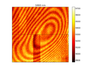
This shows an assembled flat provided by Jim C. The segments are labeled. Note that a bias correction and rudimentary gain correction have been applied. This agrees with an assembled flat he provided shown here:
Below is plotted an untrimmed version. The green box are raw data boundaries, the red box is the overscan region and the blue box is the data region.

The above images were produced using bounding boxes and offsets calculated in the code. This makes the plotted images match the orientation from Jim's example. If I use the bounding boxes in the header (commit 280194e), I get a good assembly, but it is flipped about the y-axis. I'm not sure how important that is or what I'm missing in the headers, but I believe that the above orientation does not imply that the serial direction is +ve in the +ve x direction.

Questions
Below is a list of questions to be addressed as a result of this requirements document. These are just here for historical reasons. These answers will be fleshed out in the design above.
| Question | Outcome |
|---|---|
Some of the necessary data will have to be input by the user. How should we do that?
| The result will be that we take any camera level info as config params. The rest will come from image headers. We are defining some custom header keys but they will be defaulted. Any key can be remapped using a mapping dictionary from a config file. More complicated mapping will be done through a processing step. |
14 Comments
Simon Krughoff
So in looking at example data (000-00_fe55_fe55_005.00_000_20140420032332.fits) I find that the DATASEC and TRIMSEC do not represent what I expect:
From the documentation of the mosaic keywords:
The DATASEC seems to make sense, but I don't know why TRIMSEC only goes to y of 700.
James Chiang
Right, TRIMSEC isn't part of our spec and the official sensor test code does not use it. That keyword was written by the RTS2-based data acquisition scripts, which themselves were written years ago. The RTS2 output (still) isn't compliant with LCA-10140, so we've been running an afterburner script to write out compliant keywords based on the pre-processed header contents. This script doesn't delete the extra keywords, hence the vestigial TRIMSEC keyword. If TRIMSEC is something cameraGeom would like to use, we can update the spec to include it, so that it will have correct values.
Simon Krughoff
Thanks for the explanation. I'm fine using DATASEC. I think it's more widely understood, but I think TRIMSEC should go away if it's not being used. It sounds like that is the plan.
Simon Krughoff
I've added the info we need to build a camera object, but I haven't yet link these to the header keys that will give us the information. I will start in on that tomorrow using the NOAO mosaic keys and the camera team design page.
James Chiang
Hi Simon,
Here's the use case I mentioned:
https://dev.lsstcorp.org/cgit/LSST/Camera/Sensors/eotest.git/tree/python/lsst/eotest/sensor/EOTestPlots.py
Have a look at the plot_flat(...) function near the top of that file. In that, I'm simply trying to mosaic the segment data from one of our single-sensor multi-extension FITS files. Doing the slicing and flipping with numpy arrays is surprisingly slow. I noticed yesterday that there is a Mosaic class in the DM stack. Could that be useful here without a lot of extra work?
Also have a look at
https://dev.lsstcorp.org/cgit/LSST/Camera/Sensors/eotest.git/tree/python/lsst/eotest/sensor/AmplifierGeometry.py
This tries to encapsulate some of the amplifier geometry info listed in your table above. It's used in the file translation script to get the geometry keywords right in the RTS2-produced files and in the code that uses the overscan regions to do bias-subtraction as well as some other places. It would be great if cameraGeom has similar abstractions that could be easily used instead.
Simon Krughoff
We'll actually use the code here:
https://github.com/LSST/afw/blob/master/python/lsst/afw/cameraGeom/assembleImage.py
to assemble amps into chips.
Where is the Mosaic class? It may be vestigial.
We will certainly abstract access of data regions. I think it will make the operations you've been doing to this point more straight forward.
James Chiang
Here's where I first saw a reference to Mosaic:
http://lsst-web.ncsa.illinois.edu/doxygen/x_masterDoxyDoc/afw_sec_display.html#afwSecDs9Mosaics
(This is from the doxygen of "master" last modified on 23-Oct-2014 16:17.) The class appears to live in afw.display.utils.
Simon Krughoff
Thanks. I think that may just arrange images in a grid, but I'll take a look.
Unknown User (shaw)
FWIW, in NOAO data the OBSTYPE keyword indicates the kind of observation, not the kind of detector. Typical values are: object, zero, dark, dome flat, sky flat. I don't know if the camera team associates the same semantic meaning to this keyword, but it would be a shame if they didn't.
Simon Krughoff
O.K. Thanks Dick. I think the camera team generally puts the type of test in that field. In my mind the detector type is really it's purpose in the mosaic, so I may be conflating two different concepts.
James Chiang
There is a TESTTYPE keyword that we use for that information.
James Chiang
The Camera team currently has no specification for the use of OBSTYPE in laboratory-acquired data.
Robert Lupton
The Mosaic object is used to assemble mosaics of images such as PSF stars or KL basis functions, it's not designed to assemble a set of pictures with an externally-specified geometry.
So not vestigial, but not useful for this purpose. We should clarify the docs.
James Chiang
For the record:
---------------------------------------------------------------------------------------------------------------
From: Simon Krughoff <simon.krughoff@gmail.com>
Date: Thu, 20 Nov 2014 11:20:41 -0800
Subject: Fwd: [LSST|dm-devel #10] [RFC] --Tool for creating a Camera from FITS files
To: James Chiang <jchiang@slac.stanford.edu>
Jim,
Here's the email Tim sent.
---------- Forwarded message ----------
From: Tim Jenness <tjenness@cornell.edu>
Date: Wed, Nov 5, 2014 at 9:33 PM
Subject: Re: [LSST|dm-devel #10] [RFC] --Tool for creating a Camera from
FITS files
To: Simon Krughoff <simon.krughoff@gmail.com>
Simon,
Some comments on the example camera FITS header you sent Frossie. Variable
width font may mess things up a bit.
Group related sections and separate with spacers. You can have all
blank characters in the first 8 columns:
---- Obs Id, Date, Pointing Info ----
OBJECT =3D 'G34.3 ' / Object of interest
If you add a bit of whitespace and groupings it significantly improves the
readability of the header.
Would it make sense to group all amplifier A headers together and then B
amplifier? Rather than scattering them about the file? Just seems random at
the moment:
---- Amplifier A ----
RDNOISEA=3D ...
AMPSECA =3D =E2=80=A6
---- Amplifier B ----
OBSGEO-[XYZ] headers are missing (they are the standard way of specifying
the telescope location).
The long string convention generally requires a LONGSTRN header to
indicate that this convention is being used:
PROGRAM =3D 'A DECam search for Centaurs: Probing planetary formation in th=
e
&'
CONTINUE 'outer Solar System&=E2=80=99
Run fitsverify on your example file:
Undefined values for a particular key follow the syntax:
KEYWORD =3D / Comment
Sometimes for DARKS etc you won=E2=80=99t fill in all the values (no telesc=
ope
position for example). I=E2=80=99ve seen many headers that don=E2=80=99t un=
derstand how to
implement proper undefined values in FITS and they really are painful to
see.
Used MJD and not MJD-OBS or MJD-AVG. "MJD" is not a standard header.
Is SHUTTER a boolean? Or floating point?
Why are some HIERARCH keywords upper case and others lower case?
Some headers have proper [] units but others don't. Doesn't seem to be any
logic about it.
MCLK has a typo in the unit string.
Why is HIERARCH baud_rate a string?
Does BINNING duplicate the information in BINX and BINY? Why is that needed=
?
DATE-OBS only has millisecond precision but data in the file clearly have
microsecond precision. (USEC header). MJD is in a completely different part
of the header from JD. This relates to a comment I had at the OCS
interfaces review where it wasn=E2=80=99t clear what precision was being re=
corded
in the system despite the system using PTP throughout so having
microseconds available.
CCDTEMP has no comment or units (true of the final few headers -- were they
added by other software?)
On Nov 4, 2014, at 12:18 , Simon Krughoff <simon.krughoff@gmail.com> wrote=
:
I'm forwarding this to the new devel list. I'm going to start on this in
the next couple of days, so if there are any comments, get them to me soon.
Simon
---------- Forwarded message ----------
From: Simon Krughoff <simon.krughoff@gmail.com>
Date: Wed, Oct 29, 2014 at 12:26 PM
Subject: [RFC] --Tool for creating a Camera from FITS files
To: LSST Data Management <lsst-data@lsstcorp.org>
This is a request for comment on a strawman design for a utility to create
a Camera object from FITS files. This will help the camera team in their
processing to build cameraGeom objects: e.g. ISR, assembly, but I hope it
will generally make it easier to get data going with LSST.
The page is available here:
https://confluence.lsstcorp.org/display/DM/Design+page+for+DM-1112
If at all possible, I'd like to keep comments on that page rather than in
an email thread, so please respond there.
Thanks,
Simon